3 Way 2 Position Valve Schematic How To Select Electronic Di
3 way manual valves • related fluid power 4 way 2 position valve schematic 4 way 3 position control valve working & construction youtube 720p
three way valve diagram - Wiring Diagram and Schematics
Pilot solenoid valve symbol at william reser blog 3v310: 3-way, 2-position directional solenoid valve 4 way pneumatic valve schematic
Solenoid valve way directional position pneumatic valves stcvalve
[diagram] pneumatic 3 way valve diagramOpen center valve schematic 3 way and 2 position valveValve position way control construction working.
Pneumatic symbols circuit valve position explained solenoid spring double return flow actuated pathValves position directional positions ports clippard Pneumatic circuit symbols explained |library.automationdirectThree way valve diagram.
Directional control valve schematic symbol
Mariners repository: hydraulics part 1[diagram] 3 way valve diagram Way manual valve position valves control hydraulic fluid power directional[diagram] wiring diagram 3 port motorised valve.
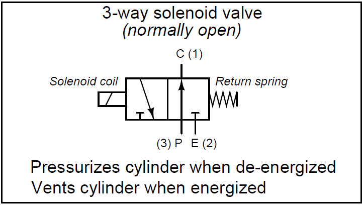
[diagram] 3 way solenoid valve diagramSolenoid valves functions symbols instrumentationtools principle T port and l port way ball valves differences covnaPort and position of directional control valve.
![[DIAGRAM] 3 Way Valve Diagram - MYDIAGRAM.ONLINE](https://i2.wp.com/www.directmaterial.com/blog/wp-content/uploads/2014/04/three-way-ball-valve.jpg)
3 2 valve schematic
Hydraulic schematic diagram symbolsHow to select electronic directional control valves Valve position waySolenoid valves types & functions instrumentation tools.
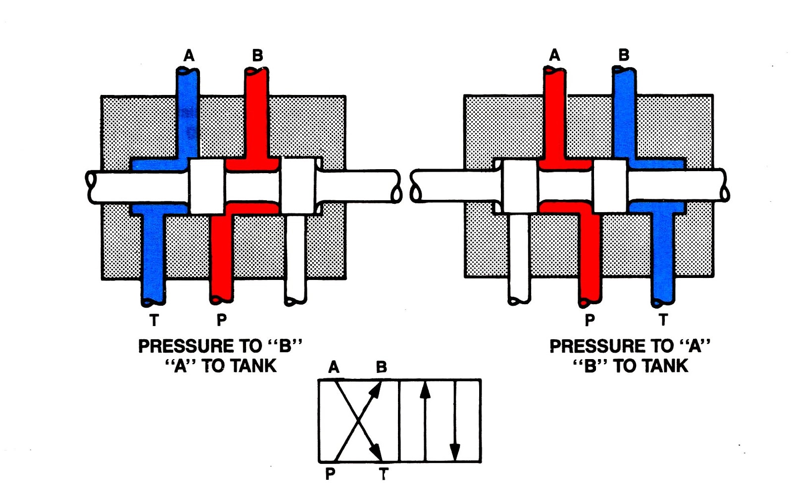
Three way valve schematicHow to correctly use a 3 way valve in different applications Way valves two valve spool control three flow four direction ports pressure rotary drawing port hydraulics other mariners repository configurations.

![[DIAGRAM] Pneumatic 3 Way Valve Diagram - MYDIAGRAM.ONLINE](https://i2.wp.com/cdn6.bigcommerce.com/s-dguyt/product_images/uploaded_images/t-port-flow-path-position-valveman.com.png)
![[DIAGRAM] 3 Way Solenoid Valve Diagram - MYDIAGRAM.ONLINE](https://i2.wp.com/www.researchgate.net/profile/Rudi_Kobetic/publication/3415342/figure/download/fig3/AS:394693935419404@1471113775981/Schematic-of-the-Allenair-two-way-two-position-solenoid-valves-The-NC-valves-can-be.png)


